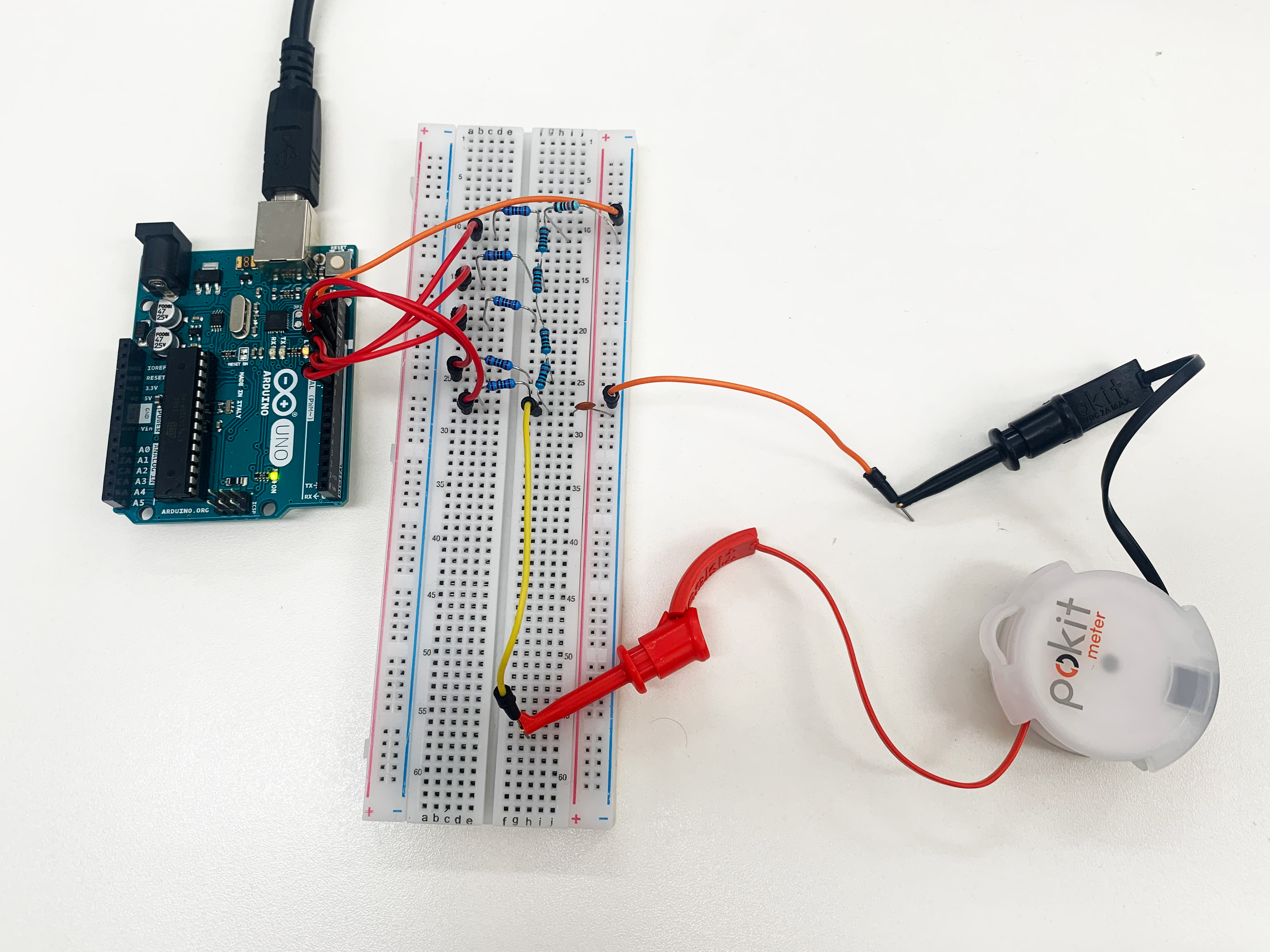
Today we will be going through how to make a signal generator using an Arduino and using the Pokit Meter to read and debug. You might be wondering why would I ever need to make a signal generator? Well, there are a couple of reasons that you might need to make one.
- As a hobbyist, it is a fun and easy project to test and hone your skills using Arduino.
- For testing – when you are creating a circuit, testing a piece of equipment (i.e. an amplifier) or testing a frequency response, it is useful to have one handy to inject the signal into the circuit or device.
We also made a video to go along with this blog post. If you wanted to check it out, click here.
What you need
To create the signal generator, you will need all the below.
- 4 x 220Ω resistors
- 5 x 1kΩ resistors
- 1 x 10kΩ resistor
- 1 x 100nF capacitor (optional extra, not in Arduino Starter kit)
- 1 x Pokit Meter
- 1 x Arduino & Breadboard
- 8 x male to male leads
These can be found using the links below:
Building the signal generator
1. Connecting your resistors
To begin, pin your 220Ω resistors onto your breadboard in a series. This is what is known as an R-2R bridge. When pinning the 220Ω resistors each end of the resistors can be put in the same pin hole.
Next, using your 1kΩ resistors, pin them perpendicular to each 220Ω resistor on the breadboard. This should start from the top of the first 220Ω resistor, then in each end connected 220Ω resistor and lastly on the end of the 220Ω series.
After all of that, you should have 1 x 10kΩ resistor left. Place this 10kΩ resistor next to the first 1kΩ resistor. If you have done this, it should be next to the first 1kΩ resistor and perpendicular to the first 220Ω resistor.
2. Connecting your leads and wiring
To begin, connect one end of your ground wire into the negative section of the bread board (on the right), next to the 10kΩ resistor. Connect the other end to the ground of the Arduino.
Next, referring to the schematic, use 5 male-to-male leads to connect the end of each 1kΩ resistor to the Arduino. As you can see in the schematic, each pin is placed with the resistor and into the various pin numbers on the Arduino. You will need to make sure each lead’s pin is going to the right pin, as incorrect placement will affect the circuit.
Lastly, you may pin the last two leads as the output leads of the circuit. Pin one of the leads connecting to the end of the 220Ω resistor series and pin the other lead to the negative of the breadboard. Respectively these are the positive and negative outputs.
Additionally, you may add a 100nF capacitor (not included in the Arduino kit) in between the output pins to allow a smoother waveform to be generated.
This is what your signal generator should look like. 
3. Load Signal generator code onto Arduino
To load the signal generator code to the Arduino you will need to download the Arduino software to your PC using the following link. Once you have downloaded this, you can then use the connecter cable you receive in your Arduino starter kit to connect your Arduino to your PC. Next, using the Arduino software, you should be able to copy and paste the signal generator code into the software and have it running on the Arduino.
4. Testing the signal generator
To begin, you must have the Arduino connected to a power source. This can be achieved by using an adaptor to connect it to a wall source or keeping it connected to your PC.
5. Take readings with Pokit Meter
Once you have finished setting up the signal generator, you are able to now use your Pokit Meter to read the signals that are being generated. To do so, you connect the wire clips to the positive and negative output leads. Then connect the Pokit Meter to the Pokit App and acquire a reading.
If you find that the waveform does not look correct, make sure all wiring and resistors are connected properly. If you did not use a capacitor, this might also be a factor as to why the waveform doesn’t look smooth.
You can reset the Arduino to change the signal being generated.
And you’re done!
These are some examples of the signals you can generate.


Schematic of Arduino Signal Generator
If you get confused with anything we have said, you can refer to the schematic we have provided down below for further reference.

If you have any questions or concerns you can comment below!
Bye for now,
Kaylen from Pokit Innovations
Comments
0 comments
Please sign in to leave a comment.